Table of Contents
Adding relays to switch lighting ON/OFF
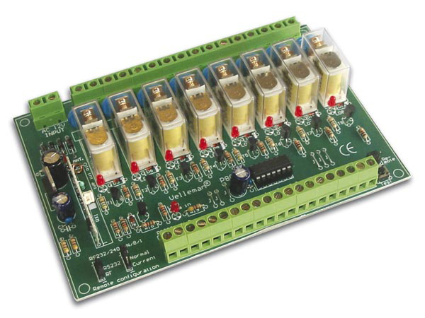
For switching lights, misting pumps, heaters etc.. I use a Velleman K8056 relay card or just regular relays (as long as the 3.3V Wemos can trigger them).
The main reason why I use the Velleman card is that if I do not it will be collecting dust on my shelf. And I have written an Arduino library years ago to easily control it using RS232 using only 1 pin.
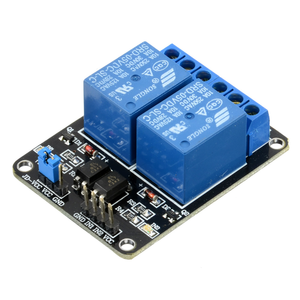
In this writeup I’ll use a simple relay board with 2 relays such as this one which is capable of switching 250V AC mains at 10Ampere which is way more than the vivarium lighting will ever use.
Wemos has special relays that easily fit onto the Wemos board or Wemos expansion board. Only downside is that these by default use pin D2 which we use for the SHT11 sensor.
This can be changed by setting the appropriate jumpers shown in the picture in the datasheet with a little drop of soldering tin.
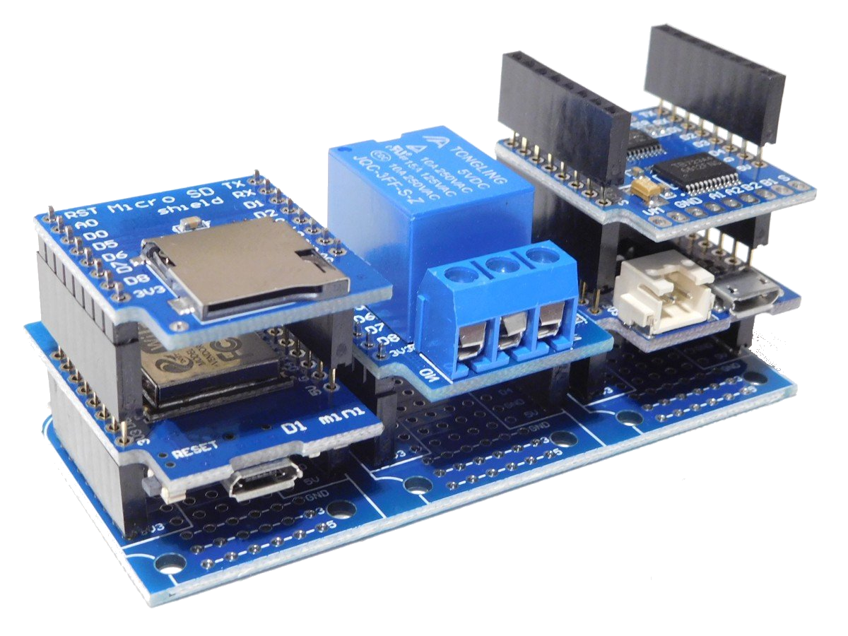
This so called trippler base could be a nice startpoint for building an actual TerraControl node. It can easily hold the Wemos and 2 relays.
The connection of these relays is very simple as all we need is a VCC, Ground and 2 datapins (one per relay).

These relays need to respond to MQTT messages sent by Node-Red so first we design a JSON payload to control them:
{
   "relay":1,
   "state":true
}
In the program that is running on the Wemos we need to change the following:
Inside MQTT_helper.h is a function called callback() and it needs to be changed to the one below:
void callback(char* topic, byte* payload, int length) {
  Serial.print("Message arrived [");
  Serial.print(topic);
  Serial.println("] ");

  StaticJsonDocument<1024> doc;
  deserializeJson(doc, payload, length);
  int relay = doc["relay"];
  bool relay_state = doc["state"];
  Serial.print("relay = ");
  Serial.println(relay);
  Serial.print("relay_state = ");
  Serial.println(relay_state);
  serializeJsonPretty(doc, Serial);

  if (relay == 1){
    if (relay_state == true){
      digitalWrite(relay1Pin, HIGH);
    }
    else if (relay_state == false){
      digitalWrite(relay1Pin, LOW);
    }
    else {
      Serial.print("Invalid data!");
    }
  }

  if (relay == 2){
    if (relay_state == true){
      digitalWrite(relay2Pin, HIGH);
    }
    else if (relay_state == false){
      digitalWrite(relay2Pin, LOW);
    }
    else {
      Serial.print("Invalid data!");
    }
  }
}
Additionally we need to add another include file named Relays.h:
#define relay1Pin D8
#define relay2Pin D7


void Relays_begin(){
	pinMode(relay1Pin, OUTPUT);
	pinMode(relay2Pin, OUTPUT);
}
In main.cpp we need to include Relays.h, and make some changes to the order of the includes to make sure we do not use functions and variable before they are declared.
The includes will look like this:
#include "Ticker.h"               // Library for scheduling tasks without using delay()
#include <ArduinoJson.h>          // Needed to store configuration as JSON: https://github.com/bblanchon/ArduinoJson
#include <Relays.h>               // Used for declarations concerning the relays
#include <WIFI_helper.h>          // Used for declarations concerning the WiFi in general
#include <MQTT_helper.h>          // Used for declarations concerning the MQTT connection
#include <Sensirion_SHT1x.h>      // Declarations for the Sensirion SHT11 Temperature/Humidity sensor
#include <DS18B20_Sensors.h>      // Declarations for the Sensirion DS18B20 Temperature sensor
Inside the setup() we need to add Relays_begin() to initialize the pins used by the relays:
void setup()
{
  Serial.begin(74880);

  // Print the Node identifier
  Serial.print("ESP Board MAC Address:  ");
  Serial.println(WiFi.macAddress());

  Relays_begin(); // initialize the relays

  setup_wifi();
  setup_MQTT();

  // Start up the DS18B20 library
  DS18B20.begin();

  // Find available DS18B20 sensors
  report_DS18B20_sensors();

  // Set the temperature resolution for each DS18B20 sensor
  for (int i=0; i<deviceCount; i++){
    DS18B20.setResolution(T[i].addr, TEMPERATURE_PRECISION_10_BIT);
    print_DS18B20_resolution(T[i].addr);
  }

  // start the timer for periodic measurements
  timerMeasurement.start();
}
Now we can use Node-Red to switch the relays ON or OFF by simply sending a JSON object thru MQTT with the topic name inTopic.
For testing I use the following nodes:
- inject node to trigger the event by sending either a 1 or a 0, set the payload in the node properties to number and make it a 1 for the first inject node and 0 for the other;
- function node to create the JSON object with the code below:
var data = {};
if (msg.payload == 1){
  data.payload = '{"relay":1, "state":true}';
}
else {
    data.payload = '{"relay":1, "state":false}';
}
return data;
- mqtt output node to send the message to the Wemos.
In the settings for the MQTT output pick the correct broker, set the topic to inTopic and select a QoS (Quality of Service) of 2 to make sure the message is always going to be received. Optionally you can set the retained check to make sure that if the node is offline it will get the message when it is online again.
Wire all the nodes together as displayed below:
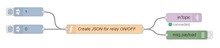
After the flow is deployed you can click on the little blue square in front of the inject node to trigger the sending of the message.
The Wemos should receive it and switch the relays ON/OFF accordingly.